Ladder logic and programmable logic controller (PLC) scanning, binary coded decimals, and reusable codes are among PLC programming tips offered by Control Engineering editorial advisory board member Frank Lamb, the founder of Automation Consulting Services Inc., a Control Engineering content partner. Featured below are tips on PLC programming from three different viewpoints.
Ladder Logic and PLC Scanning
Almost all programmable logic controllers (PLCs) worldwide handle scanning in the same way. First, the CPU reads the physical inputs into a memory table, usually called the “input table.” This table is then used as the program is evaluated. There are different types of registers that are used in different platforms; these registers are updated as the logic is processed left to right on each rung and top to bottom within each routine. This includes updating an output table, which will later be used to drive the physical devices connected to the PLC. The program might call different subroutines for different purposes, and it can be important in what order routines are called. Depending on where memory registers and output tables are updated, the physical outputs could be delayed by up to two scans. In either case, the program meanders through the different routines as they are called before returning to wherever they were called from and eventually ends up at the end of the original cyclic routine. Most programs use an initial cyclic routine that is used to call all of the other routines. Some programs, however, run on a periodic basis instead of a continuous program. This is uncommon, though. Most programs use a continuous program configuration that runs as fast as it can. After executing all of the code, evaluating the logic, and updating all of the tables (except for the input tables, which were written at the beginning of the scan), the resulting output table or register contents are written to the physical outputs. How long does this take? That depends on the platform (speed of the processor), how much code there is in the program, and the types of instructions used. Sometimes programmers will use loops in the program or make repetitive calls to the same routines. All of this has an effect on the total scan time. There is usually documentation available indicating the execution time for different instructions, but there’s no point in trying to add up all of the code to make an estimate on length. It simply is available for reference. The scan time can take as long as 80 ms. If the scan time is longer than about 50 ms (for a machine control project) then the user should be looking for a more powerful processor or ways to make the code more efficient. Beyond 50 ms, the effect on output reaction for a machine control project starts to be noticeable; for a process control project this may not matter. 
Binary-coded decimals and PLCs
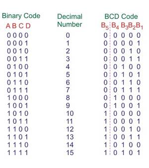
Binary-coded decimals (BCDs) are a class of binary encodings, which are usually represented by four or eight bits. It’s only humans who need to add up all those individual bits in our registers to convert them to base 10 because that’s the way we’re programmed to think. Back in the days before touchscreens, seven-segment displays and thumbwheel switches were used as a numerical interface between humans and PLCs. Even before the PLC, these devices were the only graphical way to interface with circuits numerically. Users could move plugs around like in the days of ENIAC (the first electronic general purpose computer), but it was a lot easier to view and adjust decimal numbers with these devices. The problem was, they were very input/output (I/O) intensive. Each thumbwheel segment required four inputs (+ power), while each 7-segment display required four outputs (+2 power connections). Still, it was a lot easier to interface directly with signed or unsigned integers in decimals than use pushbuttons and pilot lights. A common complaint is the math; every data type has to be explicitly declared on the platform, and converted if data types are not equivalent. Not only that, but the standard timer and counter data types incorporate BCD into their data structures. This is because the structures go all the way back to when people had to deal with things like these thumbwheels and seven-segment displays. In fact, the timer setpoints are still entered as “S5T#3S” for a 3-second setpoint. The timer uses three BCD digits (12-bits) and two extra bits for the time base. This is also true for the counters, meaning that they only count from -999 to +999. Each four-digit section can only carry bit values from 0000 to 1001; for the next value, rather than indexing to 1010, (“10? in signed or unsigned decimal or “A” in hexadecimal), the next bit gets bumped to the next section of bits. This means that the last six combinations of bits (A-F) are effectively wasted-not possible in the BCD structure. The BCD structure or base also is still usable in many of the newer touchscreens, but most programmers tend to choose an integer base to express decimal numbers. BCD is sort of like DOS; engineering schools still touch on it, but people really don’t know where it comes from. Hopefully referring back to those old thumbwheels and seven-segment displays will help clear up some of the mystery and “why” of BCD. 
Advantages of reusable code for PLCs
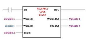
Many programmers base their knowledge and abilities on their experience with Allen-Bradley products from Rockwell Automation since much of the installed base in manufacturing consists of A-B PLCs. Rockwell Automation’s ControlLogix family was a huge jump in PLC capabilities with enhancements such as being tag-based, allowing the use of user-defined data types (UDTs), and add-on instructions (AOIs). Tags could also be made local to each program, allowing them to be duplicated for re-use. All of those capabilities, except for being tag-based, already existed years before that on other platforms. IEC 61131 for programming languages has existed since 1993 or so, and other PLCs leveraged that early on. One of the most important differences between the older, register-only based systems and the more modern ones is the ability to build re-usable code blocks. Platforms that support this must have these three features: 1. Local vs. global variables. Re-usable code must have variables that apply to each instance of the code; ideally only formatting the data once for the original code. What this means is that a list of tags or symbols should not have to be re-named for each instance or call. For instance, duplicating a subroutine several times and iterating the addresses inside of it, though it saves time, isn’t really re-usable code. 2. User-defined data types (UDTs). Creating UDTs allows structures to be built that can be exported from one application to another. They allow components to be described using generic terms such as “Speed,” “Start,” and “Reject.” UDTs don’t require tag-based systems, but they do require an advanced use of symbols. 3. Protectable self-contained blocks. It is important that the code be contained in a block that allows variables to be passed in and out, and also protected so that users can’t change a specific instance of it. This requires a password or software key. These are just some of the requirements. Other features like being able to write code in other IEC-compliant PLC languages such as structured text also help make platforms much more powerful and “rapid code development” friendly. Regardless of whether the platform uses subroutines with local variables or customizable instructions, reusable code is a critical part of creating powerful programs quickly. Many platforms allow reusable code, and each has its own unique methods. For more guidance on PLC selection and programming contact one of CBT’s hi-tech specialists today!


